
Installing the MD_Parola and MD_MAX72XX Arduino libraries
To control the MAX7219 display we will be using two awesome Arduino libraries created by Marco Colli from MajicDesigns. The MD_Parola library can be used to create many different text animations like scrolling and sprite text effects. This library depends on the MD_MAX72XX library which implements the hardware functions of the LED matrix.
This are some functions and features of the library:
- Left, right, or center text justification
- Text scrolling with entry and exit effects
- Control display parameters and animation speed
- Multiple virtual displays (zones) in each string of LED modules
- Support for hardware SPI interface
- User-defined fonts and/or individual characters substitutions
- Support for double-height displays
- Support for mixing text and graphics on the same display
Marco has been working on this library for several years and has written some excellent tutorials on his blog. The source code and documentation for the libraries can be found here:
- MD_Parola source code on GitHub
- MD_Parola documentation
- MD_MAX72XX source code on GitHub
- MD_MAX72XX documentation
You can install the libraries via the Library Manager of the Arduino IDE. Go to Tools > Manage Libraries… or type Ctrl + Shift + I on Windows. The Library Manager will open and update the list of installed libraries.
Manage libraries
Search for ‘MD_MAX72XX’ and look for the libraries by majicDesigns. Select the latest version and then click install. Make sure that you install both the MD_MAX72XX library and the MD_Parola library.

Library manager
About the MAX7219 LED driver
The MAX7219 LED driver can be used to control 7-segment displays up to 8 digits, bar-graph displays, or 64 individual LEDs. The driver communicates with the Arduino through SPI so you only need three wires to control the display.
Since the MAX7219 can control a maximum of 64 LEDs, the maximum size dot matrix display it can drive is 8×8 pixels. However, you can daisy chain multiple drivers and matrices together and easily control much larger displays like 8×32, 8×64, or even bigger. Still, you only need three wires to control all of the ICs so you need very few I/O pins of the Arduino.
Below you can find the specifications of a typical MAX7219 8×32 LED dot matrix display.
MAX7219 LED dot matrix display specifications
| Operating voltage | 5 V |
| Display driver | MAX7219 x 4 |
| Brightness levels | 16 |
| Display dimensions | 32 x 128 x 15 mm |
| Pixels | 8×32, ⌀ 3 mm |
| Cost | Check price |
For more information, you can check out the datasheet:
MAX7219 Datasheet
Almost all of the displays I have used in the past used a 1088AS type 8×8 LED matrix. You can find a datasheet from one of the companies that makes them below:
1088AS Datasheet
The MAX7219 LED Display Driver
The MAX7219 8 digit display driver is a compact, serial input/output common-cathode LED display driver that can interface to a microprocessor (µP) to control 7-segment displays up to 8 digits, bar-graph displays, or 64 individual LEDs.
Uses for the MAX7219:
- Converting serial data to parallel data
- Reducing I/O pin usage of a microcontroller or processor
- Can control 64 LEDs using only three pins
- Preferred choice for controlling 7-segment displays
- Can be connected in serial to control more display segments
Only one external 9.53k Ohm resistor is required to set the segment current for all of the LEDs in the display.
Here is how to connect it to a 7 segment display:
The MAX7219 comes in a 24-pin DIP package:
MAX7219 Example 1 Code
Copy Sketch
MAX7219
Example 2
This sketch scrolls text left using the MaxMatrix library
using bit banged
operation (the function used is shiftout – in the library
code – this is an
automatically included Arduino function) so devices can be
used on any pins (albeit at
a slower rate than using the SPI built in hardware – requires specific pin use).
Buffer Buf7219 is defined to allow the maximum data you
use so if you use
more than 5 data bytes increase it – others just set it to
10 – but that is
confusing as it is not easy to see what it is used for
unless you read the
code.
Note: Observe
the PROGMEM qualifier
that puts data into internal programming memory and the
access function that
you must use to retrieve it memcpy_P().
Recent Articles
-
Digispark Attiny85: Easily save space using this tiny chip to replace an Uno. Learn how to program this chip using the standard Arduino IDE.
-
PCF8574: How does this device work with no Internal Control Registers? Yet it allows a processor to Read, or Write each pin very easily. Find out its Secret Here.
-
This Heart Rate Sensor Arduino Project guides you in creating a pulse rate sensor using an IR LED and a photodiode to detect a pulse from 1st principles…
-
This tutorial on Fading an RGB LED with an Arduino, shows you exactly How to wire up and control a ‘Breathing’ RGB LED, and keep the same color during fades.
-
Learn How to measure temperature using an Arduino with an NTC thermistor. How to get readings using the Steinhart-Hart equation for Maximum Accuracy.
-
Arduino String: C++ style string vs old style c string Compared.
Should you use the Arduino String class or old style c strings? Is there a memory saving? Which is easier? Find out here with a Full Serial command decoder.
Подключение 7 сегментного индикатора
ass=”wp-block-heading h3-style”>
Распиновка
7-сегментный светодиодный дисплей имеет 10 контактов. Общий вывод (com) подключается либо по схеме с общим анодом, либо по схеме с общим катодом. При подключении необходимо знать, к какому типу относится индикатор. Обычно с обратной стороны можно найти его маркировку.
Рисунок 4. Схема выводов 7-сегментного дисплея
Соединение резисторов с выводами индикатора
- Мы должны подключить резистор к каждому сегменту отдельно.
- Избегайте параллельного подключения светодиодов с одним резистором.
- Если мы подключим один резистор к параллельно соединенным светодиодам, то некоторые светодиоды будут светиться, а некоторые нет. Поскольку падение напряжения в прямом направлении отличается для каждого светодиода, то только светодиоды с наименьшим падением напряжения будут излучать свет.
Рисунок 5. Как не стоит подключать индикатор с общим катодом
Используйте напряжение, максимальный ток и прямое падение напряжения сегмента указанное в таблице технической документации.
Расчет номинала резистора
Рисунок 6. Подключение резистора к сегменту индикатора
\
Где R — резистор, подключенный последовательно светодиоду; V — напряжение источника питания; VLED — прямое падение напряжение на светодиоде; ILED — прямой ток светодиода.
Пример расчета сопротивления резистора
Напряжение питания 5 вольт. Максимальный ток составляет 20-25 мА. Ток ILED возьмем равным 10 мА (учитывая безопасный запас), так как 10 мА достаточно для свечения сегмента.


Если V = 5В и VLED = 1.7В, тогда значение сопротивления резистора равно:
\
MAX7219 Features
- It is an LED driver display IC with a 10MHz serial interface which allows the user to select the decode/No-Decode digit.
- Its operation is specified in a voltage range of +4.0 to +5.5V. Normally, the voltage supply of +5V is used.
- It provides a feature of digital and analog brightness intensity control and a 150µA shutdown mode in which the current of all segments is pulled to ground.
- It consumes very low power.
- The data is displayed on segments with a delay time of 2.2ms.
- MAX7219 works well in a temperature range of 0°C to +70°C.
- The maximum current for each segment pin is 100mA and for each DIGIT ground pin is 500mA
Other Display Options
- Monochrome 0.96” OLED Display
- Nokia5110 LCD Module
- 2.4″ TFT LCD Display Module overview
- TFT Display
- TM1637- Grove 4 Digit Display Module
- 16×2 LCD Module – Liquid Crystal Display
- 7 Segment Display
Визуальный редактор
Рассмотрим ещё один пример создания бегущей строки со словами “Я кота”. Символы для фразы уже подготовлены. Вы можете создать собственные символы и добавить в код.
Редактор для создания собственных символов для матрицы с драйвером MAX7219
Щёлкайте по квадратам для генерации кода.
Результат
byte customChar = {
	B00000000,
	B00000000,
	B00000000,
	B00000000,
	B00000000,
	B00000000,
	B00000000,
	B00000000
};
| 8×8 MAX7219 | Arduino Pin |
|---|---|
| DIN | |
| CLK | |
| CS |
Код для скетча Arduino
#include "LedControl.h"

// initialize the library
/*
  pin 12 is connected to the DIN
  pin 11 is connected to the CLK
  pin 10 is connected to CS
*/
LedControl lc = LedControl(12, 11, 10, 1);

/* we always wait a bit between updates of the display */
unsigned long delaytime = 600;
void setup()
{
  lc.shutdown(0, false);
  /* Set the brightness to a medium values */
  lc.setIntensity(0, 8);
  /* and clear the display */
  lc.clearDisplay(0);
}

void loop()
{
  writeText();
}

void writeText() {
  // Символы для фразы Я люблю кота
  byte Ya = { B00111111,B00100001,B00100001,B00111111,B00000101,B00001001,B00010001,B00100001};
  byte love = { B00000000, B01100110, B10011001, B10011001, B10000001, B01000010, B00100100, B00011000};
  byte K = { B01000100,B01001000,B01010000,B01100000,B01010000,B01001000,B01000100,B01000010};
  byte O = {B00011000, B00100100, B01000010, B01000010, B01000010, B01000010, B00100100, B00011000};
  byte T = { B00111110,B00001000,B00001000,B00001000,B00001000,B00001000,B00001000,B00001000};
  byte A = {B00111000, B01000100, B10000010, B11111110, B10000010, B10000010, B10000010, B10000010};


  /* Я */
  for (int i = 0; i
Ещё один визуальный редактор для создания анимационных эффектов LED Matrix Editor.
Библиотека LEDMatrixDriver
В описании говорится, что библиотека LEDMatrixDriver является наследником устаревшей LedControl. Также доступна через менеджер библиотек. На Гитхабе есть несколько примеров с применением библиотеки. Я использовал пример SetPixel, который заполняет все ряды светодиодов светом поочерёдно.
При подключении использовались пины DIN=11, CS=9, CLK=13.
Дополнительные материалы
Arduino-er: Arduino Uno: scan LED Matrix in Timer Interrupt (+видео)
Arduino-er: Beating Heart animation on 8×8 LED Matrix + Arduino Uno (+видео)
Arduino 8×8 LED Matrix Pong – YouTube (исходники)
Старая библиотека, давно не обновляется.
07.Display: RowColumnScanning
В состав Android IDE входит пример для светодиодной матрицы File | Examples | 07.Display | RowColumnScanning. Суть в следующем – с помощью двух потенциометров считываем показания с аналоговых выводов в интервале от 0 до 7. Показания от первого потенциометра указывают на вывод из ряда, а от второго на вывод из колонки матрицы. Таким образом, мы можем крутить ручки двух потенциометров и выбирать, какой светодиод из матрицы следует включить.
Я предлагаю упростить пример. Уберём потенциометры и удалим функцию readSensors() из скетча. Теперь, чтобы включить любой светодиод, нужно указать номер ряда и номер колонки в двумерном массиве и подать на него LOW.
Включим светодиоды по диагонали.
MAX7219 and MAX7221 Datasheet
[MAX7219 Datasheet : http://datasheets.maximintegrated.com/en/ds/MAX7219-MAX7221.pdf]
Note: The
MAX6950/MAX6951 is an
equivalent device for a 3 or 3.3V system but there are
differences so read the
datasheet carefully e.g. no cascading – importantly you
can not use them for an
internally wired 7segment display but you do have access
to each LED segment
(probably using a charlieplexing
method – although this is not stated directly). The
MAX6950/MAX6951 is
available only in a surface mount package.
Display MAX7219 Brightness Control
There are two ways to control the display brightness.
- Via current setting resistor (Rset).
- By using an internal control register.
Note: There is no
requirement for
adding current limiting resistors to each column as the
LED output intensity is
controlled by a PWM signal i.e. the LEDs are turned on for
a shorter time to
dim them – and this time is controlled by a register.
How to use MAX7219?
A 16-bit data is sent at serial DIN input. On the rising edge of a clock input, this data is shifted into the 16-bit shift register integrated inside this chip. Then this data is passed to either the digit or control registers on the rising edge of LOAD/CS. Data is sent out at the serial output pin on the falling edge of CLK. The pins D0 to D7 contain data that is to be passed and D8 to D11 pins contain the address of the register.
Simple Example Circuit
A simple circuit is shown below which shows the MAX7219 connection with a microprocessor.
The display brightness can also be controlled. Connect an external resistor (RSET) between pins 18 and 19. The value of this resistor can either be fixed or variable for adjusting the brightness adjustment of the display panel. The intensity of light can also be controlled digitally through a pulse-width modulator present inside a chip. It has an in-built register known as scan-limit which sets the number of digits to be displayed, from 1 to 8.
Decoder Mode Register
It has another register known as decode mode register which is used to sets BCD code B or no-decode operation for each digit. A high logic level is used to select code B decoding and low level for no-decode operation. In case of code B, the decoder looks only at only D3-D0. D7 pin is used to set the decimal point. When this pin is High, it turns the decimal point on. The truth table for code B is given below.
LedControl Examples
Edit the following (examples in the install directory)
for the pins used
(save as your own):
- LCDemoCascadedDevices.ino (2286 Bytes) Individual
pixel control – does work. - LCDemo7Segment.ino (2766 Bytes) – no idea what this is
doing! - LCDemoMatrix.ino (3584 Bytes) – Sort of works with
backwards text.
Note: This library
does not scroll
text. Examples are for one 64 led unit only – you can edit
them to use the
other.
This library can be made to work by adding your own code
on top but you have
to write all the display shifting yourself – has been
done!. One problem I had
with that code is that it uses the deprecated type (where
prog_uchar is no
longer used in the new Arduino compiler):
prog_uchar
To get round this add the following to the top of the
code:
#define prog_uchar const char
The other problem is that the scroll direction is
left/right. The assumption
is that you are using the LEDs correctly i.e. rows are
horizontal and columns
are vertical (this is correct for the displays that plug
directly together i.e.
when laid end to end rows and columns are in the correct
orientation). The ones
shown in the wiring diagram below have rows and columns
swapped – the top of
the LED display (pin diagram above) is the left side.I am using ones in which it easier to have rows as
vertical and columns as
horizontal (see below). Would be nice to have a code switch
to change this around
as I have done on the non MAX7219 project here: (This LED matrix project
directly controls a
8×8 64 LED matrix using 8 transistors (COLUMNS) and 8 data
drives (ROWS)).
Железо:
Далее составляем принципиальную схему. Для этого открываем datasheet на светодиодный дисплей. Из всех «многа букафф» ценность представляют несколько таблиц и рисунков. Это:1) электрооптические характеристики:
Из которых следует, что наш дисплей действительно имеет общий катод и зеленый цвет свечения2)Назначение и нумерация выводов:
Из первого рисунка узнаем про нумерацию выводов, расположение сегментов и разрядов на индикаторе (например, что первый разряд (разряд десятков) имеет обозначение D1, а разряд единиц D2. Из таблицы узнаем, что вывод катода второго разряда – это вывод 13 на индикаторе, а анодам сегментов a, b, c, d, e, f, g соответствуют выводы 11, 10, 8, 6, 5, 12, 7. Вывод первого катода – 14. Но анодов для него всего 2: это сегменты b и c (15 и 3 выводы соответственно). Это значит, что на первом разряде можно засветить только цифру 1
Остальные выводы неподключенные (это немаловажно, т.к. позже я через них буду проводить дорожки, не боясь что-либо закоротить).3)И напоследок:
Убеждаемся, что ток 1 сегмента должен быть 20mA (это стандартная величина для подобных дисплеев и обычных светодиодов
На основе этой величины подбираем сопротивления, для ограничения тока.Далее составляем принципиальную схему:
Кроме светодиодного дисплея и микросхемы сдвигового регистра, которые я описал ранее, в схеме присутствуют 9 резисторов для ограничения тока до 20мА на каждый сегмент. Микросхему я установил на панельку. Также используются два разъема (один 9ми штырьковый для подключения платы напрямую к Arduino при вытянутой с панельки микросхеме и один 5ти штырьковый для подключения через микросхему сдвигового регистра.Также из-за особенности дисплея выводить в первом разряде только единицу и чтобы не использовать вторую микросхему 74HC595 я вместо «точки» подключил сегменты «b» и «c» первого разряда дисплея. Теперь при появлении на выходе Q7 сигнала высокого уровня будет зажигаться в разряде десятков цифра «1».Номера выводов дисплея я в схеме не указывал, т.к. для каждой модели дисплея они разные и брать их надо с даташита.Чтобы легче было собирать – по-быстрому в sprint layout выбрал шаг сетки 2.54мм и набросал плату.
Скачать ее можно тут.Вот как выглядит готовая плата:
К Arduino она подключается следующим образом:


Библиотеки
- Max72xxPanel + Adafruit-GFX, нужно установить обе библиотеки
- GyverMAX7219 + GyverGFX, нужно установить обе библиотеки. При установке GyverMAX7219 через менеджер библиотек GyverGFX подтянется автоматически
- GyverMAX7219 – базовое взаимодействие с матрицей, возможность очистить и поставить точку по координатам
- GyverGFX – вывод геометрии (линии, прямоугольники, окружности, кривые), вывод картинок из памяти, вывод текста (русский и английский шрифт нескольких размеров)
Объявление матрицы выглядит так:
//MAX7219 < W, H, CS > mtrx;    // подключение к аппаратному SPI
// пример: UNO / Nano (CLK - D13, DI - D11, CS - любой пин)

//MAX7219 < W, H, CS, DATA, CLK > mtrx; // подключение к любым пинам
// W и H - количество МАТРИЦ по горизонтали и вертикали
// CS, DATA, CLK - номера пинов
Для начала работы нужно вызвать . Опционально можно настроить яркость через и повернуть матрицу . На матрицу можно выводить:
void dot(int x, int y, uint8_t fill = 1);                           // точка, fill - GFX_CLEAR/GFX_FILL/GFX_STROKE
void fastLineH(int y, int x0, int x1, uint8_t fill = 1);            // вертикальная линия, fill - GFX_CLEAR/GFX_FILL/GFX_STROKE
void fastLineV(int x, int y0, int y1, uint8_t fill = 1);            // горизонтальная линия, fill - GFX_CLEAR/GFX_FILL/GFX_STROKE
void line(int x0, int y0, int x1, int y1, uint8_t fill = 1);        // линия, fill - GFX_CLEAR/GFX_FILL/GFX_STROKE
void rect(int x0, int y0, int x1, int y1, uint8_t fill = 1);        // прямоугольник, fill - GFX_CLEAR/GFX_FILL/GFX_STROKE
void roundRect(int x0, int y0, int x1, int y1, uint8_t fill = 1);   // скруглённый прямоугольник, fill - GFX_CLEAR/GFX_FILL/GFX_STROKE
void circle(int x, int y, int radius, uint8_t fill = 1);            // окружность, fill - GFX_CLEAR/GFX_FILL/GFX_STROKE
void bezier(uint8_t* arr, uint8_t size, uint8_t dense, uint8_t fill = 1);   // кривая Безье
void bezier16(int* arr, uint8_t size, uint8_t dense, uint8_t fill = 1);     // кривая Безье 16 бит. fill - GFX_CLEAR/GFX_FILL/GFX_STROKE
void drawBitmap(int x, int y, const uint8_t *frame, int width, int height, uint8_t invert = 0, byte mode = 0);  // битмап
void setCursor(int x, int y);           // установить курсор
void setScale(uint8_t scale);           // масштаб текста
void invertText(bool inv);              // инвертировать текст
void autoPrintln(bool mode);            // автоматический перенос строки
void textDisplayMode(bool mode);        // режим вывода текста GFX_ADD/GFX_REPLACE
Чтобы матрица обновилась – нужно вызвать .
Library MaxMatrix
This is a manual install to the <location of your
sketches>/libraries
– unzip to this directory.
This second library I used (MaxMatrix). This provides a simple
interface and multiple
ways of scrolling the text:
- shiftLeft – probably the only function you need to use
(see ) - shiftUp
- shiftRight – see code notes (below) as this one does
not work that well. - shiftDown
For most users wanting to left scroll scrolling text this
library works well
but it only works with the modules oriented as in the
breakout board shown in
the wiring diagram below i.e. only with COLS
and ROWS swapped. It will not work correctly with
plug together modules
that have correctly oriented rows and columns (ones with a
surface mount
MAX7912 mounted on the back).
Warning: This
library will not work (
text will not scroll to left) unless the 1088AS LED is
oriented with rows
vertical and columns horizontal () and
each display is aligned beside the other (see ).
This diagram shows what is going on:
MaxMatrix Example
Code size used (3482 Bytes)
(with ).
Software Setup
for
MAX7219
IDE Version Used : 1.6.4Board used : Arduino Uno R3Device Used : MAX7219LED Display: 64 element LED Matrix (8×8) – Part No.
1088AS.
Parts for MAX7219
project
- 2off – MAX7219 (on breakout board).
- 2off – 64 element LED Matrix (8×8) – Part No. 1088AS
(on breakout board). - 2off – 10k resistor (on breakout board).
- Arduino Uno R3.
- 2off – 10uF Electrolytic (on breakout board).
MAX7219
Example 1
This code uses 2 units and uses the internal SPI module.
The display
intensity is slowly scaled up and down while random pixels
are lit/unlit on the
display – quite good in a darkened room! It is based on
code found here :
https://gist.github.com/nrdobie/8193350
…but modified to show operation with 2 units.I have deliberately left the code as a basic operational
code without
algorithms e.g. not setting the number of display units,
as this allows you to
see fundamental operation of the system – and it keeps
everything in one
file.
Warning: You might
hypnotize yourself
with this random output!
To use one unit – disconnect
the last
one! – and hit reset.
Note: The
serial debug output slows
the code – remove it (and the delay(10) ) to see VERY
fast operation.
Note how code is added twice to fill up the two serially
connected MAX7219
(internal) shift registers – see functions:
maxTransferCMD
maxTransferDATA
Немного теории:
Светодиодный дисплей с общим катодом (ОК) можно представить как 8 светодиодов соединенных в одну точку катодами. Схематически это выглядит так:
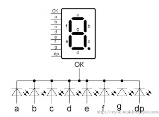
Катод подключается к «минусу» питания (общему проводу, массе), а подавая напряжение на выводы анодов можно засветить сегменты от «a» до «g» или сегмент «dp» (точку). Зажигая разные комбинации сегментов визуально воспринимаются как цифры или знаки. Например, включенный сегмент «g» воспринимается как «-» (минус), одновременно включенные сегменты «abcdef» – «0», «bc» – «1» и т.д.Сдвиговый регистр 74HC595 представляет собой преобразователь входного последовательного сигнала на входе Ds (выв. 14), в выходной параллельный на выходах Q0-Q7 (выводы 15, 1-7), позволяя этим самым увеличить количество выводов микроконтроллера.
Синхронизация передачи данных происходит при помощи тактирующего пина SHcp (вывод 11). Вход микросхемы STcp (вывод 12) служит своеобразной «защелкой» и позволяет после того как данные будут записаны по входу Ds, передавать сигнал на все 8 выходов одновременно. Одна микросхема может преобразовать с последовательного в параллельный 8 бит информации (В нашем случае это значит, что можно управлять не более чем 8-ю сегментами дисплея). Т.е. если нам нужно управлять 2х разрядным индикатором, тогда придется добавить второй сдвиговый регистр и соединить его вход Ds (вывод 14) c выходом Q7’ (вывод 9) первого регистра. Если 3х разрядным, то нужно 3 микросхемы и т.д.
Матрица с драйвером MAX7219
Существует более удобный вариант матрицы с драйвером MAX7219 в виде отдельного модуля. Есть полностью готовые модули, а есть вариант, когда детали поставляются в разобранном виде и нужно самостоятельно паять.
Благодаря применению SPI модуль имеет только пять выводов с двух сторон: питание, земля и три цифровых вывода.
Модули можно соединять между собой, получая большое табло.
Сначала попробуем вариант включения любого светодиода матрицы вручную. В коде используются несколько функций. Для одиночного модуля вызываем функцию maxSingle(). Если используется несколько модулей, то уберите комментарии с вызовов функций maxAll(), maxOne().
При вызове функции maxSingle() в первом аргументе указываем номер ряда, во втором число в степени двойки – 1, 2, 4, 8 и т.д.
Исходный код программы (скетча)
Arduino
// Including the required Arduino libraries
#include <MD_Parola.h>
#include <MD_MAX72xx.h>
#include <SPI.h>
// Uncomment according to your hardware type
#define HARDWARE_TYPE MD_MAX72XX::FC16_HW
//#define HARDWARE_TYPE MD_MAX72XX::GENERIC_HW
// Defining size, and output pins
#define MAX_DEVICES 1
#define CS_PIN 3
// Create a new instance of the MD_Parola class with hardware SPI connection
MD_Parola myDisplay = MD_Parola(HARDWARE_TYPE, CS_PIN, MAX_DEVICES);
void setup() {
// Intialize the object
myDisplay.begin();
// Set the brightness of the display (0-15)
myDisplay.setIntensity(2);
// Clear the display
myDisplay.displayClear();
}
void loop() {
myDisplay.setTextAlignment(PA_LEFT);
myDisplay.print(“C”);
delay(650);
myDisplay.setTextAlignment(PA_LEFT);
myDisplay.print(“I”);
delay(650);
myDisplay.setTextAlignment(PA_LEFT);
myDisplay.print(“R”);
delay(650);
myDisplay.setTextAlignment(PA_LEFT);
myDisplay.print(“C”);
delay(650);
myDisplay.setTextAlignment(PA_LEFT);
myDisplay.print(“U”);
delay(650);


![Светодиодная rgb матрица 64×32 [амперка / вики]](https://9rooms.ru/wp-content/uploads/9/2/f/92fe1634079c2e6efff530c10e9c9fae.jpeg)


myDisplay.setTextAlignment(PA_LEFT);
myDisplay.print(“I”);
delay(650);
myDisplay.setTextAlignment(PA_LEFT);
myDisplay.print(“T”);
delay(650);
myDisplay.setTextAlignment(PA_LEFT);
myDisplay.print(“D”);
delay(650);
myDisplay.setTextAlignment(PA_LEFT);
myDisplay.print(“I”);
delay(650);
myDisplay.setTextAlignment(PA_LEFT);
myDisplay.print(“G”);
delay(650);
myDisplay.setTextAlignment(PA_LEFT);
myDisplay.print(“E”);
delay(650);
myDisplay.setTextAlignment(PA_LEFT);
myDisplay.print(“S”);
delay(650);
myDisplay.setTextAlignment(PA_LEFT);
myDisplay.print(“T”);
delay(1500);
}
|
1 |
// Including the required Arduino libraries MD_ParolamyDisplay=MD_Parola(HARDWARE_TYPE,CS_PIN,MAX_DEVICES); voidsetup(){ // Intialize the object myDisplay.begin(); // Set the brightness of the display (0-15) myDisplay.setIntensity(2); // Clear the display myDisplay.displayClear(); } voidloop(){ myDisplay.setTextAlignment(PA_LEFT); myDisplay.print(“C”); delay(650); myDisplay.setTextAlignment(PA_LEFT); myDisplay.print(“I”); delay(650); myDisplay.setTextAlignment(PA_LEFT); myDisplay.print(“R”); delay(650); myDisplay.setTextAlignment(PA_LEFT); myDisplay.print(“C”); delay(650); myDisplay.setTextAlignment(PA_LEFT); myDisplay.print(“U”); delay(650); myDisplay.setTextAlignment(PA_LEFT); myDisplay.print(“I”); delay(650); myDisplay.setTextAlignment(PA_LEFT); myDisplay.print(“T”); delay(650); myDisplay.setTextAlignment(PA_LEFT); myDisplay.print(“D”); delay(650); myDisplay.setTextAlignment(PA_LEFT); myDisplay.print(“I”); delay(650); myDisplay.setTextAlignment(PA_LEFT); myDisplay.print(“G”); delay(650); myDisplay.setTextAlignment(PA_LEFT); myDisplay.print(“E”); delay(650); myDisplay.setTextAlignment(PA_LEFT); myDisplay.print(“S”); delay(650); myDisplay.setTextAlignment(PA_LEFT); myDisplay.print(“T”); delay(1500); } |
Обзор модуля светодиодного матричного дисплея 8×8 MAX7219
Существует все версии модуля светодиодного матричного дисплея 8×8 MAX7219 (MAX7219 8×8 LED Matrix Display module) – универсальный модуль (generic) и FC-16. Обе эти версии будут рассмотрены в нашей статье.
Светодиодный матричный дисплей
Модуль светодиодного матричного дисплея MAX7219 состоит из 64 светодиодов, объединенных в форме матрицы 8х8, благодаря чему им удобно управлять с помощью техники мультиплексирования. Обычный монохромный матричный дисплей 8×8 имеет 16 контактов, 8 для строк и 8 для столбцов. Его внешний вид показан на следующем рисунке.
Чип драйвера светодиодного дисплея MAX7219
Чип MAX7219 – это микросхема драйвера светодиодных дисплеев с общим катодом, которая позволяет подключать к микропроцессорам различные типы светодиодных дисплеев, начиная от семисегментных цифровых и до 8-символьных, в том числе и графические дисплеи из 64 индивидуальных светодиодов. Микросхема MAX7219 совместима с интерфейсами SPI, QSPI и MICROWIRE и имеет набор драйверов для уменьшения электромагнитных излучений.
Наиболее частой проблемой при использовании технологии мультиплексирования является то, что при ее применении микроконтроллер будет постоянно занят обновлением состояния дисплея и у него не будет свободных ресурсов для выполнения других задач. Но при использовании драйвера MAX7219 вам не стоит беспокоиться об этой проблеме поскольку большинство этих задач данный драйвер возьмет на себя. Вам необходимо будет всего лишь передавать необходимые последовательные данные по интерфейсу SPI.
MAX7219 может полностью контролировать 64 индивидуальных светодиода и одновременно он может обновлять состояние дисплея с частотой до 800 Гц. Также он позволяет управлять и яркостью свечения светодиодов дисплея – и это он может делать не прекращая выполнение других задач.
Установка яркости дисплея с помощью драйвера MAX7219
Чип драйвера дисплея MAX7219 позволяет управлять яркостью дисплея программным или аппаратным способом. Аппаратно это можно сделать с помощью резистора для настройки яркости, который находится внизу платы модуля.
Данный резистор отвечает за верхний предел тока и, таким образом, он ограничивает общую яркость светодиодов дисплея. В следующей таблице представлены номиналы этого резистора, которые вам необходимо использовать в соответствии с напряжением и прямым током для вашей светодиодной матрицы, то есть, к примеру, если у вас светодиоды на 2.5V 10 mA, то значение сопротивления данного резистора должно быть равно 59,3 кОм.
Далее в статье мы рассмотрим и программное управление яркостью свечения светодиодов дисплея.


