
Code for displaying Bitmap image on OLED using Arduino.
The method is used to display the array.
This method takes the arguments (x, y, image array, image width, image height, rotation). The (x, y) coordinates define where the image starts to be displayed.
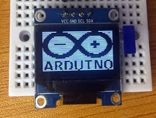
When this code is uploaded to the OLED, a monocolor image will be displayed as shown below.
I have used this display in a number of other projects which you can check out for further practice on how to use the 12C OLED display with other sensors and Arduino;
- Digital Clock using DS3231 RTC, OLED and Arduino
- DHT11 Temperature and Humidity sensor with OLED and Arduino
- MLX90614 Non-Contact Infrared Temperature Sensor with Arduino and OLED.
Graphics
There are many libraries for graphics on small displays. Typically these displays don’t have a fast refresh rate, so you can’t exactly create fast action games on them, but they can be good for simple graphic informational displays. Different display libraries will have slightingly different naming schemes for their graphics, but you can usually count on being able to draw points, lines, rectangles, circles, and sometimes rounded rects and triangles. You can generally also count on functions like vs. depending on whether you want a filled rectangle or not. All libraries will include methods for setting a color, clearing a screen, and filling the screen with a color. Most will also include commands for rotating the graphics display. Here’s the Adafruit_GFX library graphics primitives tutorial as an example.
Remember, all of your commands are only executed when you call .
Here’s a link to a graphic example that graphs the sensor reading. If you haven’t already included the Adafruit_GFX library, you will need to for this.
The Circuit
The circuit for this lab consists of:
- the microcontroller
- a potentiometer. You can use any analog sensor you choose, however.
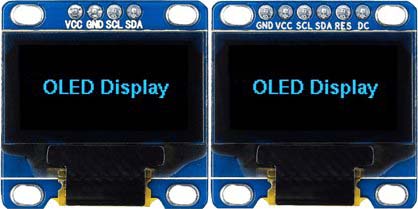
- an SSD1306 OLED breakout board
There are many breakout boards that use the SSD1306 OLED: Adafruit, Sparkfun , DFRobot, Crystalfontz, MakerFocus, Amazon, and many others. It typically comes in a 128×32 pixel version and a 128×64 pixel version. Solomon Systech makes other variations on this display as well, like the SSD1309 or the 1315. They come with different resolutions, different physical sizes, and different features.
Most of the SSD1206 displays have all blue pixels, but there are some models on the market have one section of yellow pixels and the rest blue. You can’t change the color of the pixels, so be aware of what you are buying and choose what you need. If you need a board with all blue pixels, don’t get the one with the yellow section.
Connect the display’s voltage and ground pins to your voltage and ground buses, and the I2C clock (SCL) and I2C serial data (SDA) pins to your microcontroller’s corresponding I2C pins as shown in Figure 6-7. The schematic, Figure 6, is the same for both the Uno and the Nano. For the Arduino Uno or the Arduino Nano boards, the I2C pins are pins A4 (SDA) and A5(SCL). This is the same connection for almost any I2C device.
Connect the potentiometer’s two outside connections to power and ground, respectively. Connect the middle pin (the wiper) to the Arduino’s pin A0. You’ll use the potentiometer to generate something to display on the screen.
Once you’ve got the circuit wired as shown in Figures 6-7, you’re ready to program the microcontroller.
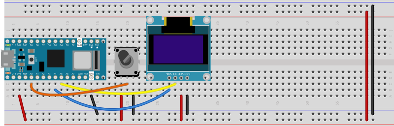 Figure 6. Breadboard view of a potentiometer and an SSD1306 OLED screen attached to a Nano 33 IoT. The potentiometer is connected to pin A0. The screen’s SDA pin is connected to pin A4 and the SCL pin is connected to pin A5.
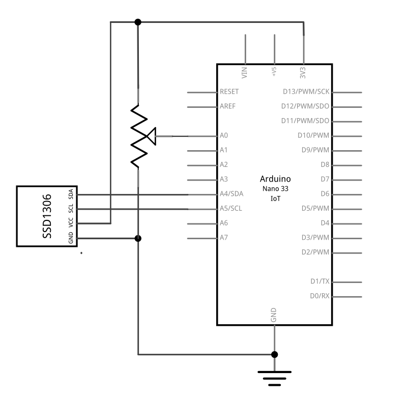 Figure 7. Schematic drawing of a potentiometer and an SSD1306 OLED screen attached to a Nano 33 IoT. The schematic is the same for an Uno. The potentiometer is connected to pin A0. The screen’s SDA pin is connected to pin A4 and the SCL pin is connected to pin A5.
Scrolling Hello World
As mentioned, being able to set coordinates outside the view screen is useful when you want to animate. One from of animation is to scroll text. Lets try it.
The connection is same as above example, copy and paste the sketch below into your Arduino program. Remember to change your constructor.
#include "U8glib.h"

//**************************************************
// Change this constructor to match your display!!!
U8GLIB_SSD1306_128X64 u8g(U8G_I2C_OPT_NONE|U8G_I2C_OPT_DEV_0);
//**************************************************

int yPos = ;

void setup() {

  u8g.setFont(u8g_font_unifont);
  u8g.setColorIndex(1); // Instructs the display to draw with a pixel on.
}

void loop() {
  u8g.firstPage();
  do {
    draw();
  } while( u8g.nextPage() );

  // If its too fast, you could add a delay
  if(yPos  83){
    // if it's too slow, you could increment y by a greater number
    yPos++;  }
  else{
    // When the yPos is off the screen, reset to 0.
    yPos = ;
  }
}
void draw(){
  u8g.drawStr( , yPos, "Hello World");
}
Running Result
A few seconds after the upload finishes, it should look like this:
Part of the magic here has to do with the picture loop (which will be examined in more detail later). But suffice to say, the loop erased the previous display and and created a new display every cycle.
Take a minute and study the code. Tinker with it. Instead from top to bottom, try scrolling from bottom to top. Now try to tinker with the X position and move the display from left to write.
Шаг 1: Дизайн
Я поставил семь сегментный светодиодный дисплей над расширителем ввода / вывода. Это экономит массу места и работает довольно неплохо, но требует немного “хитрых” дел. Смотрите “хитрый” раздел для деталей. Поскольку любой вывод из семи сегментных дисплеев может быть подключен к любому выводу расширителя ввода / вывода, вы можете спланировать наиболее удобную схему подключения и позаботиться о том, какие выводы имеют какое число в программном обеспечении. То, как я подключил семисегментные дисплеи к расширителю ввода / вывода, довольно умно, если я сам так скажу и учту очень малую площадь и минимум проводки, но это может быть немного сложно объяснить. Я сделаю все возможное и надеюсь, что фотографии помогут. Я недавно обнаружил картон и сразу влюбился в него. Я взял с рождественской открытки встроенную ретро-видеоигру с эмалированным (магнитом) проводом, которая отлично подходит для использования на картоне. Я всегда слышал, что вы должны раздеть провод наждачной бумагой. Пользователь bradsprojects рекомендует зачистку провода шариком расплавленного припоя. Я обнаружил, что даже эта удобная техника почти не нужна. Вы можете просто пойти дальше и припаять провод, даже не отрывая его. Припой абсолютно не прилипнет к лаковому покрытию, поэтому, если у вас есть хорошее паяльное соединение, вы знаете, что лак исчез. Для прохождения лака может потребоваться немного больше тепла, чем если бы вы правильно зачищали провод. Но пока связь выглядит хорошо, это хорошо. Чем больше размер проволоки, тем больше тепла потребуется для прожига. Я использовал больший датчик для заземления и подключения питания и меньший датчик для всего остального. Все мои эмалированные провода пришли из комплекта Radio Shack номер 278-1345.Вы можете заметить, что я припаял расширитель ввода / вывода прямо к плате. Кажется, что все используют сокеты для своих микросхем, независимо от того, намереваются ли они когда-либо поменять микросхему. Кроме того, что люди, которые выдают за замену песни и танцы, используют розетки, другая причина – это страх слишком сильно нагревать микросхему и жарить ее. Вот в чем дело, микросхемы предназначены для пайки. Они могут принять тепло. Вы постоянно видите сотни микросхем на профессионально сделанных платах во всей вашей любимой электронике. Все они спаяны с использованием метода оплавления, который нагревает микросхему больше, чем пайка одного пина за раз. Так что не бойтесь, припаяйте эту микросхему прямо к вашей плате. Вы сэкономите место и получите лучшее соединение. И до тех пор, пока вы не задержитесь на булавке смехотворно долго, микросхема будет в порядке. Извините за напыщенную речь, но я думаю, что это нужно сказать. Я разработал этот проект в Google Sketchup, потому что очень полезно посмотреть, как части сочетаются друг с другом, и Sketchup настолько прост и удобен в использовании. Я рад, что сделал это, потому что изображение из Sketchup лучше, чем любое, которое я сделал с моей камерой. Вы заметите, что каждая таблица данных для каждой детали, которую вы когда-либо видели, имеет точные размеры. Это делает создание его в SketchUp легким. Если вы хотите получить совет по Sketchup, сделайте все в масштабе х10. То есть, если деталь составляет 0,3 дюйма, в Sketchup сделайте ее 3 дюйма. У Sketchup есть небольшие проблемы с тонкими маленькими проводами и деталями с небольшими размерами. Делать все в масштабе х10 помогает. Вы всегда можете распечатать его в масштабе х10, чтобы он соответствовал размеру на листе бумаги, что-то еще, что мне нравится делать, чтобы я мог получить реальное представление о размере. Файл Sketchup прилагается, если вы заинтересованы.
OUR EVALUATION RESULTS:
These are interesting modules to work with since they have full graphical capability but can also pack a lot of textual information into a very small form factor.
These modules are breadboard friendly with a 4-pin header on the back that can be inserted into a solderless breadboard or a 4-pin female connector can be used to connect to it if the display is to be mounted. The display is very thin, so be sure to press on the header pins when applying pressure to insert them into a breadboard and not press on the glass.
Follow these simple steps to get the display up and running.
Connect the display
This is simple, just connect VCC to 5V (or 3.3V) to match the MCU and connect GND to ground. The I2C lines just connect to the same lines on the MCU so SCL connects to SCL and SDA connects to SDA.
Install Libraries
Install the following 2 libraries if they are not already installed on your computer. These can be installed from within the Arduino IDE.
“Adafruit SSD1306”
“Adafruit GFX Library”
Download and run program
This program just prints some text to the display which is the most common use for the display. To see a demo of the full graphical capability, you can also run the sample program that is installed with the Adafruit SSD1306 library.


SSD1306 128 x 32 I2C Test Program
/**************************************************************************
SSD1306 128x32 I2C test

This simple program initializes the display and prints small text to
four different lines on the displays.

Connect display Vcc to 3.3 or 5V to match MCU and GND to ground
Connect display I2C SCL to MCU SCL and SDA to MCU SDA
 **************************************************************************/

#include <Wire.h>
#include <Adafruit_GFX.h>
#include <Adafruit_SSD1306.h>

#define SCREEN_WIDTH 128 // OLED display width, in pixels
#define SCREEN_HEIGHT 32 // OLED display height, in pixels

// Declaration for an SSD1306 display connected to I2C (SDA, SCL pins)
Adafruit_SSD1306 display(SCREEN_WIDTH, SCREEN_HEIGHT, &Wire);

//===============================================================================
//  Initialization
//===============================================================================
void setup() {
  Serial.begin(9600);

  // SSD1306_SWITCHCAPVCC = generate display voltage from 3.3V internally
  if(!display.begin(SSD1306_SWITCHCAPVCC, 0x3C)) { // I2C Address 0x3C for 128x32
    Serial.println(F("SSD1306 allocation failed"));
    for(;;); // Don't proceed, loop forever
  }

  // Clear the buffer, set small font size and print 4 lines of text to display
  display.clearDisplay();
  display.setTextSize(1);                    // Set for small font
  display.setTextColor(WHITE);
  display.setCursor(,);                    // Set cursor to upper left
  display.println("Line 1: Printing line");  // Println moves the cursor down
  display.println("Line 2: Printing line");
  display.println("Line 3: Printing line");
  display.println("Line 4: Printing line");

  // Show the display buffer on the screen. You MUST call display() after
  // drawing commands to make them visible on screen!
  display.display();
}
//===============================================================================
//  Main
//===============================================================================
void loop() {
}
Подключение модуля OLED к Arduino Uno
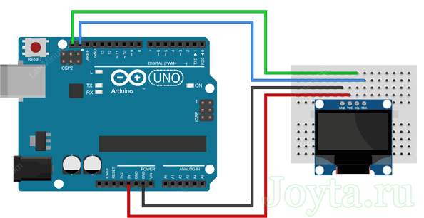
Прежде чем мы перейдем к загрузке кода и отправке данных на дисплей, давайте подключим дисплей к Arduino Uno.
Схема подключения довольно проста. Начните с подключения контакта VCC к выходу 5V на Arduino и GND к земле
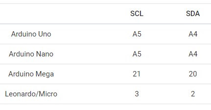
Теперь остались выводы, которые используются для связи по I2C. Обратите внимание, что каждая плата Arduino имеет разные контакты I2C
На платах Arduino с маркировкой R3 SDA (линия передачи данных) и SCL (линия синхронизации) находятся на разъемах рядом с выводом AREF. Они также известны как A5 (SCL) и A4 (SDA).
Если у вас MEGA, контакты будут другие! Используйте цифровые 21 (SCL) и 20 (SDA).
На следующей схеме показано как все должно быть подключено:
Open OLED Display Arduino Example Sketch
After installing the two libraries, as described above, new example sketches are found in the Arduino IDE. These example sketches are found under File → Examples → Adafruit SSD1306 from the top menu of the Arduino IDE. Under File → Examples, scroll down to find the section called Examples from Custom Libraries to find the Adafruit SSD1306 examples.
Open the OLED Example Sketch
Open the ssd1306_128x32_12c example sketch from the above menu. The full menu navigation to this sketch is File → Examples → Adafruit SSD1306 → ssd1306_128x32_12c
Run the Example OLED Sketch
After opening the ssd1306_128x32_12c example sketch, load it to the Arduino board with the OLED wired, as already explained. If the wiring is correct, the OLED will start showing a demo that displays various text and graphics on the screen.
Fault Finding
The only things that can really go wrong are 1) incorrect wiring, 2) faulty display, or 3) incorrect I2C address.
An I2C address of 0x3C is set for the OLED display in the example sketch. If your display uses a different I2C address, this must be changed in the sketch.
Change the I2C address at the following line of code if your OLED display uses a different address.
if(!display.begin(SSD1306_SWITCHCAPVCC, 0x3C)) { // Address 0x3C for 128x32
“Hello World” by 0.96″ 128×64 I2C OLED display

In this example,we will show how to simply light an I2C OLED display by using an Osoyoo UNO board.
Connection
Before you write the code you have to build the circuit. To do this, connect the pins as follows:
| Osoyoo UNO | LCD1602 |
| GND | GND |
| 5V | VCC |
| A4 | SDA |
| A5 | SCL |
Note:
- For Mega2560: the I2C connections are on SDA=20 and SCL=21. So go ahead and wire these up, along with the two power leads to the 5V and GND terminals.
- For Arduino Leonardo: connect SDA to digital pin 2 and SCL to digital pin 3 on your Arduino.
From sketches of Fritzing, you can look at the connections to be done in a simpler way:

Code Program
After above operations are completed, connect the Arduino board to your computer using the USB cable. The green power LED (labelled PWR) should go on.Open the Arduino IDE and choose corresponding board type and port type for you project. Then load up the following sketch onto your Arduino.
#include "U8glib.h"

U8GLIB_SSD1306_128X64 u8g(U8G_I2C_OPT_NONE|U8G_I2C_OPT_DEV_0);  // I2C / TWI

void draw(void) {
  // graphic commands to redraw the complete screen should be placed here
  u8g.setFont(u8g_font_unifont);
  //u8g.setFont(u8g_font_osb21);
  u8g.drawStr( 30, 10, "Hello!");
  u8g.drawStr( 50, 35, "by");
  u8g.drawStr( 10, 56, "www.osoyoo.com");
}

void setup(void) {
  // flip screen, if required
  // u8g.setRot180();

  // set SPI backup if required
  //u8g.setHardwareBackup(u8g_backup_avr_spi);

  // assign default color value
  if ( u8g.getMode() == U8G_MODE_R3G3B2 ) {
    u8g.setColorIndex(255);     // white
  }
  else if ( u8g.getMode() == U8G_MODE_GRAY2BIT ) {
    u8g.setColorIndex(3);         // max intensity
  }
  else if ( u8g.getMode() == U8G_MODE_BW ) {
    u8g.setColorIndex(1);         // pixel on
  }
  else if ( u8g.getMode() == U8G_MODE_HICOLOR ) {
    u8g.setHiColorByRGB(255,255,255);
  }
}

void loop(void) {
  // picture loop
  u8g.firstPage();
  do {
    draw();
  } while( u8g.nextPage() );

  // rebuild the picture after some delay
  delay(50);
}
Basic Program Flow – The Picture Loop
In ‘setup’ we first select the font we want to use. The library supports many different fonts and we will experiment with another later.
After selecting the font, we establish that drawing something means that we want to turn a pixel on. We did this with ‘u8g.setColorIndex(1)‘.
The U8glib graphic library uses something called a picture loop. The picture loop begins with ‘u8g.firstPage()‘ and ends with ‘u8g.nextPage()‘.
The picture loop is a requirement within the graphics library.
Within this picture loop, you can use a variety of graphics commands. In our loop we make a call to ‘draw()‘. In this function we instruct the display to print ‘Hello World’.
Модуль OLED диспля на основе драйвера SSD1306
В основе модуля лежит мощный однокристальный CMOS контроллер SSD1306. Он может общаться с микроконтроллером несколькими способами, включая I2C и SPI .
Протокол SPI, как правило, быстрее, чем I2C, но требует большего количества контактов ввода/вывода микроконтроллера. В то время как I2C требует только два контакта и может использоваться совместно с другими периферийными устройствами I2C. Это компромисс между экономией выводов и скоростью.

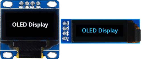
Благодаря универсальности контроллера SSD1306, модуль поставляется в разных размерах и цветах: например, 128×64, 128 × 32, с белыми OLED, синими OLED и двухцветными OLED. Хорошей новостью является то, что все эти дисплеи взаимозаменяемы.
Требование к источнику питания
Для работы OLED-дисплею не нужна подсветка, поскольку он излучает свой собственный свет. Именно поэтому дисплей имеет такой высокий контраст, чрезвычайно широкий угол обзора и может отображать глубокий уровень черного цвета.


Отсутствие подсветки значительно снижает ток потребления. В среднем дисплей потребляет около 20 мА , хотя это зависит от того, какая часть дисплея задействована.
Рабочее напряжение контроллера SSD1306 составляет от 1,65 до 3,3 В, в то время как для OLED-панели требуется напряжение питания от 7 до 15 В. Все эти различные требования к питанию решаются путем использования схемы Charge Pump. Это позволяет легко подключить модуль к Arduino или любому 5-вольтовому логическому микроконтроллеру без использования преобразователя логического уровня.
Организация памяти SSD1306
Независимо от размера OLED модуля драйвер SSD1306 имеет встроенную память объемом 1 КБ (GDDRAM). Эта область памяти разбита на 8 страниц (от 0 до 7). Каждая страница содержит 128 столбцов / сегментов (блок от 0 до 127). И каждый столбец может хранить 8 бит данных (от 0 до 7):
8 страниц x 128 сегментов x 8 бит данных = 8192 бит = 1024 байт = 1 Кб памяти

Каждый бит представляет собой определенный OLED пиксель на экране, который может быть включен или выключен программно.
Installing necessary Libraries.
Before writing any code for interfacing the OLED I2C display with Arduino, you need to install the “adafruit_GFX.h” and the “adafruit_SSD1306.h” libraries.
Download: Adafruit GFX library .
- Unzip the .zip folder you have downloaded and rename the Adafruit-GFX-Library-master folder to Adafruit_GFX_Library (take note of the change from “-” to “_”)
- Move the Adafruit_GFX_Library folder to your Arduino IDE installation libraries folder
Download: Adafruit_SSD1306 library.
- Unzip the .zip folder you have downloaded and rename the Adafruit-GFX-Library-master folder to Adafruit_SSD1306
- Move the Adafruit_SSD1306 folder to your Arduino IDE installation libraries folder
Finally, re-start the Arduino IDE
Arduino 128 x 32 OLED I²C Libraries for SSD1306 and Graphics Functions
Two Arduino libraries must be installed in the Arduino IDE to start using the display. The SSD1306 driver library is used to initialize the display and provide low level display functions. The GFX library provides graphics functions for displaying text, drawing lines and circles, etc. Both these libraries can be installed from within the Arduino IDE.
Install the SSD1306 Driver Library
Start the Arduino IDE application. Use the top menu bar to select Tools → Manage Libraries… This opens the Library Manager dialog box.
In the Library Manager dialog box, type SSD1306 in the search field, as shown in the image below.
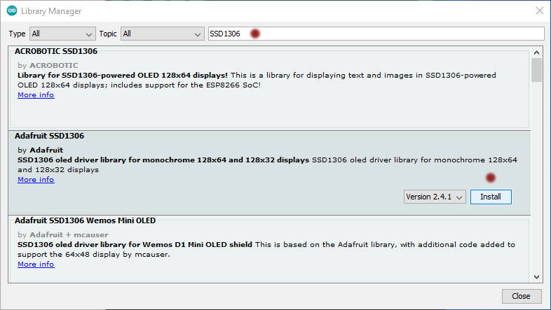 Select the SSD1306 Driver in the Arduino IDE
Hover the mouse cursor over the Adafruit SSD1306 item, and then click the Install button that appears.
Leave the Library Manager dialog box open to install the GFX library next.
Install the GFX Library
With the Library Manager dialog box still open from the above step, type GFX in the search field.
Hover the mouse cursor over the Adafruit GFX Library item in the Library Manager dialog box. Click the Install button that appears. This installs the GFX library.
OLED I2C Module
These displays are small, only 0.96″ diameter, but very readable due to the high contrast of an OLED display. This display is made of 128×64 individual white OLED pixels, each one is turned on or off by the controller chip. No back-light is required for this display because it makes its own light which reduces the power required to run the OLED. Its Visual Angle is greater than 160°. It needs only 2 I/O Port to Control,since this display uses the I2C common interface for easy plug and play usage – meaning you can connect it without the need for wires – just plug it straight in to your device.
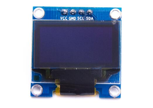
The screen comes with a nice screen protector with a tab to easily remove it after installation. The PCB is prepared with 4 reasonable-sized holes in the corners for fixation and a 4 pin header already installed for powering and communicating with the display. It can be connected directly to an Arduino without any additional parts.
Program the Microcontroller
There are many libraries available for controlling the SSD1306 OLED screens. Adafruit’s SSD1306 library works well with all the SSD1306 displays, both the 128×64 and 128×32 models. Adafruit’s library is consistent with many of their other display libraries, and they make a lot of them. So it’s a good place to start. It doesn’t work with other SSD13xx models though. For example, Sparkfun makes a Micro OLED with the SSD1309, which has a 64×48 resolution. It requires a different library.
The u8g2 library by Oli Kraus, is intended as a universal monochrome display library for OLED, eInk, TFT, and other displays. It supports some SSD130x boards, but not all. It’s a pretty good library, but lacks some of the features of the Adafruit library. The examples included here use the Adafruit library. You’ll also need the Adafruit_GFX library which supports graphics across a number of small displays.
Import the Libraries
At the start of your sketch, import the libraries and set up a variable to hold the display driver instance like so:
#include <Wire.h>
#include <Adafruit_SSD1306.h>
#include <Adafruit_GFX.h>

const int SCREEN_WIDTH = 128; // OLED display width, in pixels
const int SCREEN_HEIGHT = 64; // OLED display height, in pixels

// initialize the display:
Adafruit_SSD1306 display(SCREEN_WIDTH, SCREEN_HEIGHT);
Initialize the Display
In the setup, you need to check that the display is working. If it fails, it’s a good idea to stop and notify the user. Since there’s no user interface in this basic sketch, you’ll use the Serial Monitor.
void setup() {
  // initialize serial and wait for serial monitor to open:
  Serial.begin(9600);
  if (!Serial) delay(3000);
  // first parameter of begin() sets voltage source.
  // SSD1306_SWITCHCAPVCC is for 3.3V
  // second parameter is I2C address, which is
  // 0x3C, or 3D for some 128x64 modules:
  if (!display.begin(SSD1306_SWITCHCAPVCC, 0x3C)) {
    Serial.println("Display setup failed");
    while (true);
  }
  Serial.println("Display is good to go");
}
Print to the Display
You can print to the display by giving it a text size and cursor position and then using or . The loop below reads analog input 0, then prints the time in seconds on the first line and the sensor reading on the second.
The function which actually updates the display is called . All of the other functions update a buffer in the microcontroller’s memory. So you can make all the changes you want with commands like , , , and so forth, but you will only see the changes when you call . This is typical of many display libraries.
In the code below, you’ll clear the display, then set the size to twice the default, then move the cursor to the top left. Then you print the seconds since the sketch started, move the cursor down a line, and print the analog 0 sensor reading. Finally, you push it all to the display using :
void loop() {
  int sensorReading = analogRead(A0);
  // clear the display:
  display.clearDisplay();
  // set the text size to 2:
  display.setTextSize(2);
  // set the text color to white:
  display.setTextColor(SSD1306_WHITE);

  // move the cursor to 0,0:
  display.setCursor(0, 0);
  // print the seconds:
  display.print("secs:");
  display.print(millis() / 1000);

  // move the cursor down 20 pixels:
  display.setCursor(0, 20);
  // print a sensor reading:
  display.print("sensor:");
  display.print(sensorReading);
  // push everything out to the screen:
  display.display();
}
Here’s a link to the full sketch.
The SSD1306 is a monochrome display, but you still have to set the color to see anything display, because the library defaults to no colors. For a list of what and the other constants in the library mean, see .
Create and Display Custom Characters
If you find the characters on the display dull and boring, you can create your own custom characters (glyphs) and symbols for your LCD. They are extremely useful when you want to display a character that is not part of the standard ASCII character set.
As discussed earlier in this tutorial a character is made up of a 5×8 pixel matrix, so you need to define your custom character within that matrix. You can use the createChar() function to define a character.
To use you first set up an array of 8 bytes. Each byte in the array represents a row of characters in a 5×8 matrix. Whereas, 0 and 1 in a byte indicate which pixel in the row should be ON and which should be OFF.


All these user defined characters are stored in the CGRAM of the LCD.
CGROM and CGRAM
All Hitachi HD44780 controller based LCDs have two types of memory – CGROM and CGRAM (Character Generator ROM and RAM).
CGROM is non-volatile memory and cannot be modified whereas CGRAM is volatile memory and can be modified at any time.
CGROM is used to store all permanent fonts that are displayed using their ASCII codes. For example, if we send 0x41 to the LCD, the letter ‘A’ will be printed on the display.
CGRAM is another memory used to store user defined characters. This RAM is limited to 64 bytes. For a 5×8 pixel based LCD, only 8 user-defined characters can be stored in CGRAM. And for 5×10 pixel based LCD only 4 user-defined characters can be stored.
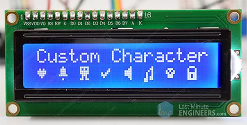
Custom Character Generator
Creating custom characters has never been easier! We have created a small application called Custom Character Generator. Can you see the blue grid below? You can click on any 5×8 pixel to set/clear that particular pixel. And as you click, the code for the character is generated next to the grid. This code can be used directly in your ESP32 sketch.
| byte Character = |
| { |
| 0b00000, 0b00000, 0b01010, 0b11111, 0b11111, 0b01110, 0b00100, 0b00000 |
| }; |
Your imagination is limitless. The only limitation is that the LiquidCrystal_I2C library only supports eight custom characters. But don’t be discouraged, look at the bright side, at least we have eight characters.
ESP32 Example Code
The following sketch shows how you can create custom characters and print them on an LCD.
You will see the following output on the LCD:
Code Explanation:
After the library is included and the LCD object is created, custom character arrays are defined. The array consists of 8 bytes, each byte representing a row of a 5×8 LED matrix. In this sketch, eight custom characters have been created.
Let’s examine the array as an example. You can see how the bits (0s and 1s) are forming a heart shape. 0 turns the pixel off and 1 turns the pixel on.
In setup, a custom character is created using the function. This function takes two parameters. The first parameter is a number between 0 and 7 to reserve one of the 8 supported custom characters. The second is the name of the array.
Next in the loop, to display the custom character we simply use the function and pass it the number of the character we reserved earlier.


